Home Donate New Search Gallery Reviews How-To Books Links Workshops About Contact
Apt Power Amplifier 1
(1979-1987)
© 2011 KenRockwell.com. All rights reserved.

Apt Power Amplifier 1 (about $300 used). enlarge. This free website's biggest source of support is when you use these links, especially this link directly to the Apt Power Amplifier 1 at eBay (see How to Win at eBay), when you get anything, regardless of the country in which you live. Thanks! Ken.
December 2011 Audio Reviews All Reviews
Apt Holman Preamplifier Review (complete)
![]()
12/2011
29.75 dB gain = 30.72557x
92.0545 mV = 1 W out
0.920545 V = 100W out
8 ohm setting:
1V in = 117.9 W out
1.03V in = 125W out at 0.1% THD (still green)
1.04V in = 127W out at 0.41% THD (still green)
1.045V in = 128W out at 0.6% THD (just turning red)
1.27V 10mS peak = 54.5V peak = 38.54V RMS = 186W RMS burst power
35W idle
36W at 1 WPC
412W at 100WPC out
A-weighted noise:
Left |
Right |
|
| Input fed from 5 Ω source impedance | -82.5 dBV |
-84.7 dBV |
| No input connection | -72 dBV |
-64.7 dBV |
Unweighted noise, AC coupled:
Left |
Right |
|
| Input fed from 5 Ω source impedance | -73.5 dBV |
-78.8 dBV |
| No input connection | -63.5 dBV |
-56.5 dBV |
DC offset
Measured into 8 Ω when fed from a 5 Ω source impedance:
Left |
Right |
-11.2 mV |
-7.5 mV |
Measured into 8 Ω with no input connested:
Left |
Right |
-11.2 mV |
-7.5 mV |
Damping Factors and Output Impedances
All the fancy math below confirms is that this amplifier has the same output source impedance as of 16 AWG speaker wire, in other words, any further reduction is insignificant.
Damping Factors at 8Ω
Left |
Right |
|
50 Hz |
||
1 kHz |
||
20 kHz |
Output Impedances
Left |
Right |
|
50 Hz |
nn mΩ |
nn mΩ |
1 kHz |
nn mΩ |
nn mΩ |
20 kHz |
nn mΩ |
nn mΩ |
Method and raw data
Voltage drop when applying an 8 Ω load:
Left |
Right |
|
50 Hz |
-0.0630 dB |
-0.0520 dB |
1 kHz |
-0.0603 dB |
-0.0522 dB |
20 kHz |
-0.0992 dB |
-0.0785 dB |
R source = (R load/attenuation ratio) - R load.


At 1W.

At 50W.

At 100W.

At 1W.

DFD at 1W.

DFD at 50W.
7/2011
These are just some measurements for now. The right (yellow) channel is out of spec for distortion, so I need to work on it.

THD vs WATTS into 8 ohms, 8-ohm position.

THD vs WATTS into 8 ohms, 8-ohm position.

Frequency Response into 8 ohms, 8-ohm position.

Infrasonic Frequency Response into 8 ohms, 8-ohm position.

SMPTE IMD into 8 ohms, 8-ohm position.

DFD at 1W into 8 ohms, 8-ohm position.

DFD 10 W into 8 ohms, 8-ohm position.

DFD at 100W into 8 ohms, 8-ohm position. This is probably clipping; I'll redo this.

DFD 50W into 8 ohms, 8-ohm position.
Power (at 120.7-120.5 VAC RMS input)
Red lights indicate clipping very, very well, easier than I can see on a scope!
burst power: 10 cycles of 1 kHz (10 mS) into 8 ohms at clipping:
High (8 ohm) posiiton
56.5 V Pk (40.0v rms or 200W) no bed
55 V Pk (38.9v rms or 189W) Bed: 1 W, 0.1v in, 3V out
52 V Pk (36.77V RMS or 169W) W (0.316v in, 10 V out) bed
low posiiton (4 ohms)
42.5 V Pk (30.05V rms = 113W) no bed
41.5 V Pk (29.35v rms or 107.5 W) with 1 W (0.1v in, 3V out) bed
39.5 V Pk (27.9 v rms or 97.5 W) with 10 W (0.316v in, 10 V out) bed
SMPTE IM
.0029/0.005 1W (0.935V)
10W (0.296V in): 0.0075/0.0197%
92W 0.1%
100W 2.9% (0.94V)
Output
DC Offset -8, -10 mV DC
Noise -78.5, -80.3 dBV A-weighted
![]()
Audio magazine, October 1979, pages 42 and 186 ("coming soon").
Audio magazine, October 1980, page 14, left side.
everyngin below is from somethign else.
Introduction top
Intro Specifications Measurements Usage Recommendations
I use Adorama, Amazon, Ritz, B&H, Calumet, J&R and ScanCafe. I can't vouch for ads below.
|


Perspective
The Apt Holman Preamplifier is the most well thought-out stereo preamplifier ever designed.
It was designed at the very height of recorded music's reign as the dominant form of home entertainment (home video was still years away), and was designed by none other than the brilliant Tom Holman, the inventor of 5.1 audio and the inventor of THX motion picture sound.
The name "Apt" comes from its definition as "an appropriate and intelligent solution to the task at hand." Newer preamplifiers today are mostly 25-pound billet aluminum cases filled with fluff: ordinary analog circuits controlled digitally with showy vacuum fluorescent displays, but missing many of the important control features and superior audio performance of the Holman Preamplifier. Instead of chasing idiotic things that consumers think are important but aren't, like what kind of wire's inside, the Apt Holman Preamplifier concentrates on what's far more important, like where those wires are connected and the analog circuity around them.
Sound
The Apt Holman
Mechanical and Electrical
It's got a 10-foot power cord, fHolman thought of everything.
no power switch
Rated Specifications top
Intro Specifications Measurements Usage Recommendations
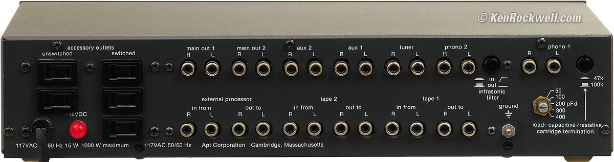
Inputs
Line
All line inputs are 50 kΩ in parallel with 330 pF.
Unselected inputs are terminated with 2.2 kΩ.
Maximum input level: 10 V RMS (+20 dBV or +22 dBm).
3 line-level inputs.
2 tape monitor loops.
1 external processor loop, for a total of six line-level and two phono inputs!
Gain, Polarity and Volume Control
gain from line inputs.
Outputs
Two MAIN
Output Levels
2 V RMS
Frequency Response
20 - 20,00
High Filter (only active with Tone Controls selected)
-3 dB at 8 kHz.
Distortion
Less than
Noise (all A-weighted RMS)
Line
-106 dB
Hum
Typically
Crosstalk
< -65
Power
120V AC, 50-60 Hz. (240V AC with internal wiring change)
95-135 V AC OK. Below 95 V AC won't trigger the unmute relay. (190-270 V AC at 240 V setting.)
Rated less than 15 W power consumption.
Rated 100 mA RMS current consumption at 120V AC.
125 mA (1/8 A) internal slo-blo pigtail fuse.
I measure 9 W power consumption.
10 foot unpolarized power cord, but oddly the accessory outlets are polarized.
Two unswitched and three switched outlets, rated 1kilowatt maximum.
Size
, WHD overall.
Weight
10.5 pounds (4.8 kg).
12 pounds (5.4 kg), packed.
Quality
Hand-made in Boston, Massachusetts, USA.
It's attached to the bottom, hand-signed by the man who inspected your preamplifier, and hand-signed by the man who tested it.

Bottom, The Apt Holman Preamplifier. enlarge.
For detailed blow-ups, here's the left side and the right side.
Price
Catalog price* |
(in period dollars) |
|
1977 |
$1,550 |
$417 |
1978 |
$1,550 |
$450 |
1979 |
$1,560 |
$502 |
1980 |
$1,350 |
$493 |
1981 |
$1,430 |
$575 |
1982 |
$1,350 |
$575 |
1983 |
$1,475 |
$648 |
2011 |
* corrected for inflation in 2011.
Measurements top
Intro Specifications Measurements Usage Recommendations
Frequency Response Maximum Output Distortion Gain & Balance
Noise Crosstalk Tone Controls Filters Tape Outputs Phono Preamp
I used a state-of-the-art Rohde &Schwarz UPL for these measurements.
Unless mentioned otherwise, they are measured with the Holman Preamplifier set to unity gain (about noon to 1 o'clock on the volume control), measured from the AUX 1 input to the MAIN 1 output, and loaded with the 200k Ω load of the Rohde &Schwarz UPL.
The traces are color coded for the Left Channel and for the Right Channel. When they don't lie on top of each other, it's due to channel imbalance.
Frequency Response: +0, -0.25 dB top
Frequency Response, tone defeated, Apt Holman Preamplifier.
It's flat to +0, -0.25 dB from 20 - 20,000 Hz, and that's including the protective DC and RFI filters. This preamp isn't designed for lab flatness; it's designed to make the system sound great by removing inaudible out-of-band crud that can cause audio distortion.
I'll cover the response of the filters and tone controls in the Tone Control section.
Maximum Output Levels measurements top
8 ohm, 120 V input
upper
left 123.5W RMS
right 124.00 W
lower
left 81.32 W RMS
right 82.0 W
Distortion measurements top
THD SMPTE IM DFD Gain Linearity
THD, Apt Holman Preamplifier, 200 mV RMS at 1 kHz.
Distortion harmonics, Apt Holman Preamplifier, 200 mV RMS at 1 kHz.
THD vs. Frequency measurements top
THD versus frequency at 1 V RMS, Apt Holman Preamplifier, tone controls defeated.
I have no idea why there is a dip above 10 kHz, unless the dominant distortion harmonics are high-order and suddenly stopped by a filter somewhere. This is measured D2 - D9 with a 110kHz maximum bandwidth.
THD versus frequency at 1 V RMS, Apt Holman Preamplifier, tone controls in-circuit.
THD vs. Level measurements top
THD versus level at 1 kHz, Apt Holman Preamplifier, tone controls defeated.
THD versus level at 1 kHz, Apt Holman Preamplifier, tone controls in-circuit.
SMPTE Intermodulation Distortion measurements top
SMPTE (60/7k Hz 4:1) IMD versus level, Apt Holman Preamplifier.
Difference-Frequency Distortion measurements top
DFD, 19/20 kHz 1:1 at 1V, Apt Holman Preamplifier, tone controls defeated.
DFD, 19/20 kHz 1:1 versus level, Apt Holman Preamplifier, tone controls defeated.
Same as above, but in dB: DFD, 19/20 kHz 1:1 versus level, Apt Holman Preamplifier, tone controls defeated.
Low-Level Linearity measurements top
Gain versus signal level, Apt Holman Preamplifier, tone controls active.
Gain versus signal level, Apt Holman Preamplifier, tone controls defeated.
These look sloppy more due to noise than any real nonlinearity; these aren't digital preamps and therefore should have no problems with linearity at every level; that's why they're called analog. The first trace was made with only 32 generator-sourced levels, while the second was made with 16 readings averaged per level, and measured at 640 levels, taking over an hour to plot.
Gain, Tracking and Balance measurements top
Gain top
Cold
Left |
Right |
|
Unloaded |
29.717 dB |
29.782 dB |
8 Ω (upper) |
29.65 dB |
29.60 dB |
8 Ω (lower) |
29.65 dB |
29.60 dB |
-0.066 dB drop 8 ohms left, -0.054 dB right = 61 mΩ left (DF 123), 50 mΩ (DF 160) right.
Warm ( 1 watt output for a few hours)
Left |
Right |
|
Unloaded |
29.718 dB |
29.779 dB |
8 Ω (upper) |
29.620 dB |
29. 676 dB |
8 Ω (lower) |
29.610 dB |
29. 682 dB |
Left |
Right |
|
8 Ω drop (upper) |
0.082 dB |
0.084 dB |
8 Ω drop (lower) |
0.095 dB |
0.089 dB |
Tracking (Left-Right channel balance versus volume control setting) top
Right channel level versus left channel, vs. volume control setting. (positive means image moves to right.)
The stereo image never varies as the volume is changed. Poorer amplifiers often skew the stereo image several dBs or more at the lowest volume settings, while the superb attenuation circuit of the Apt Holman Preamplifier keeps the channels balanced to within about a third of a dB at every setting.
Balance measurements top
The balance control attenuates the lesser channel, leaving the other alone. It works exactly like that: the one channel varies by less than 0.03 dB, while the other is attenuated.
Taking the detent as a reference, here is the imbalance imparted by the balance control at various positions:
Position |
Imbalance |
Noon |
0.0 dB (reference) |
11 or 1 o'clock |
1.25 dB |
10:30 or 1:30 o'clock |
3.5 dB |
10 or 2 o'clock |
4.5 dB |
9 or 3 o'clock |
8.5 dB |
8 or 4 o'clock |
20 dB |
Full left or right (7 or 5) |
85 dB |
Noise measurements top
Measured as driven from the muted output of the Rohde &Schwarz UPL, with its 5Ω unbalanced source impedance:
Volume Setting |
System gain |
Relative attenuation |
Output Noise, A-weighted |
Noise added by tone controls at zero* |
Maximum |
17.84 dB |
0.00 dB |
-93.6 dBV |
0.0 dB |
4 |
12.36 dB |
-5.47 dB |
-98.1 dBV |
+0.15 dB |
7 |
7.99 dB |
-9.84 dB |
-101.0 dBV |
+0.4 dB |
12 |
0.82 dB |
-17.01 dB |
-103.8 dBV |
+0.8 dB |
18 |
-9.80 dB |
-27.62 dB |
-105.0 dBV |
+1.5 dB |
22 |
-19.58 dB |
-37.40 dB |
-105.1 dBV |
+1.3 dB |
28 |
-40.40 dB |
-58.22 dB |
-105.1 dBV |
+1.4 dB |
Minimum |
-95.41 dB |
-113.26 dB |
-105.3 dBV |
+1.4 dB |
* The tone controls come after the volume control. The output noise was measured with the tone controls defeated. When they are active, they can add an inaudible amount of extra noise as shown in the last column. When active, setting the treble control up or down all the way can vary the noise by a few dB either way, and the high filter can drop it a half dB.
To convert these dBV readings into signal-to-noise ratios, add the voltage of your signal. For instance, a CD player's maximum output is +6 dBV, so with -104 dBV of noise, there is a 110 dB signal-to-noise ratio. I also measured the unweighted noise, AC-coupled in a 22 kHz bandwidth, and it was exactly 3 dB greater than the A-weighted values.
Crosstalk measurements top
Channel Separation
Channel separation versus frequency, Apt Holman Preamplifier.
This is measured in the right channel looking for leakage from the left channel. It measured the same with the channels reversed.
The impressive thing is how much separation we have when we realize that as soon as the Stereo Mode Control is take off its center detent, that separation goes out the window by design. It is not trivial to maintain such deep separation and have a variable control to mix the channels.
Idle Input Rejection
When one input is selected, but other inputs have signal, how much feeds through to the output?
With a 1 V RMS input at 1 kHz to the AUX 1 input, here's what fed-through to the output when other inputs are selected:
Left |
Right |
|
| PHONO 1 selected | -55.99 dB |
- 56.94 dB |
| PHONO 2 selected | -88.9 dB |
-78.4 dB |
| TUNER selected | -92.35 dB |
-75.09 dB |
| AUX 2 selected | -88.57 dB |
-91.14 dB |
Muting measurements top
The po
Usage top
Intro Specifications Measurements Usage Recommendations
Red lights on at about 0.5 VDC up to about 1 Hz.
Notes to myself - don't publish these:
the proper procedure for adjusting the bias (seems like it was only yesterday.....) :
needed:
rms voltmeter
8 ohm 250W noninductive load
HP-339B distortion analyzer (or equiv)
dual channel oscope
test setup:
amp out to dummy load, oscope channel A, analyzer input, voltmeter
amp in to analyzer oscillator
analyzer residual to scope ch B (vert mode chop, trig source ch A)
settings:
scope A 1V/div
scope B 1v/div (to start with)
horiz 10us/div
osc 20khz 95mV out (adjust for 2.85Vrms out of amp)
amp module bias to minimum (ccw)
analyzer input to 5V input range
procedure:
with 1W 20khz out, let amp idle for 5-10min (this test was done at the factory to an amp still warm from burn-in test, so the warm-up wasn't usually needed)
adjust trig for a stable scope picture with two cycles showing (IIRC it was 1/12 cycles with 2 pos peaks and 1 neg)
adjust scope ch B gain for a clear picture of the residual
the residual will have spikes at zero crossing
slowly increase bias until zero crossing spikes just disappear
that's the bias adjustment
as a starting point, you could adjust it to 15-20mV between emitters on an NPN-PNP pair on the output devices with no load/ no signal. it will get rid of most but not all of the crossover notch and provide a temperature stable operating point for the output devices. the distortion method is the proper way to set the bias. the 20mv method is the "safe" way to do it without a distortion analyzer. it biases the output devices for 15-20mA (you have 1 ohm between emitters) idle current.
make sure all of the mounting hardware for the transformer is tight, as well as the front panel screws. another thing to check if it keeps up, there were two different transformers used. the original one was dipped in a silicone/slate mixture, giving the whole transformer a dark grey color, and damping any magnetic "slap" very well. the newer one was dipped in a waxy varnish, and the winding wrap paper is a tan color. these made a little bit of noise, and i guess with time you might get some of the windings or core laminations getting a little bit loose. the only fix would be to re-dip the transformer in varnish. after all this time it's also possible that the big filter caps are drying out and need to be replaced. the rest of the amp could probably do with a re-cap also.
leave the white wire as-is. the magnetically induced distortion is nulled out by moving the V+ and V- leads around between the board and heat sink while watching the 20khz distortion residual on an o-scope. once you find the best null, you lock them down with hot-melt glue. we used a BIC pen body (the hexagonal shaped ones were good and strong) with V-notches cut in the end to manipulate the wires with. just be careful around the bias transistor and the collector posts of the output transistor sockets.
since the amp has been worked on, you might want to run it up to full power at 20 khz and move the wires around that pass behind the amp module boards to null out magnetically induced distortion. we used BIC pen bodies with triangular notches cut in the ends as "wire tweakers" . and then hot-glue (using high temp glue) the wires in place.
you might want to use a small dot of super glue to keep the VAS transistors from dropping their heat sinks
There are 3 adjustments, bias, offset and the load impedance sensing circuit. bias is done at 1 watt out, 20khz, adjust with a distortion analyzer until the crossover notch in the analyzer just disappears (too much bias will result in the distortion rising again, as well as too high an idle current). offset is done with the servo disabled (a jumper across the servo's integrating cap), no signal, adjust for +/- 10mv. the impedance adjustment is done at 200hz, into 5 ohm loads, and i think 10Wrms and the impedance switch at 8 ohms. adjust until the impedance light barely lights.
check to see if the display board has a fish paper shield behind it
IIRC it was to run the amp at half power 200 hz into a 5.1 ohm load and check that the load impedance LED lights (or it might have been full power into a 5.1 ohm load (at least a 200W resistor)). the load impedance indicator adjustment is on the protection board.
something like 50K up to 80C, then began to decrease rapidly in resistance to reduce the overall gain of the amp from 30 to something closer to 15 or 20,
http://www.pbase.com/rjones5296/apt_1&page=all
http://www.diyaudio.com/forums/solid-state/70261-apt-1-power-amp-undeservedly-forgotten-8.html
Recommendations top
Intro Specifications Measurements Usage Recommendations
Hey, for $300 or so today, the Apt Holman Preamplifier is an incredible steal for stereo music enjoyment.
The only thing missing would be to make it two inches wider to bring it up to the standard 17," and then adding a selectable presence EQ control:

Rockwell-modified Apt Holman Preamplifier. enlarge.
I designed and built this one-of-a-kind variation in 1983, complete with a presence tone control with selectable frequency and bandwidth. It now resides in das Museum der Tonaufnahmetechnik (The Museum of Sound Recording Technology) in Munich, Germany.
Of course I've never used a preamplifier, preferring instead to plug the variable outputs of a CD player or iPod directly into a power or headphone amplifier.
If you've found this report helpful, this free website's biggest source of support is when you use these links, especially this link directly to the Apt Holman Preamplifier at eBay (see How to Win at eBay), when you get anything, regardless of the country in which you live. Thanks! Ken.
More Information
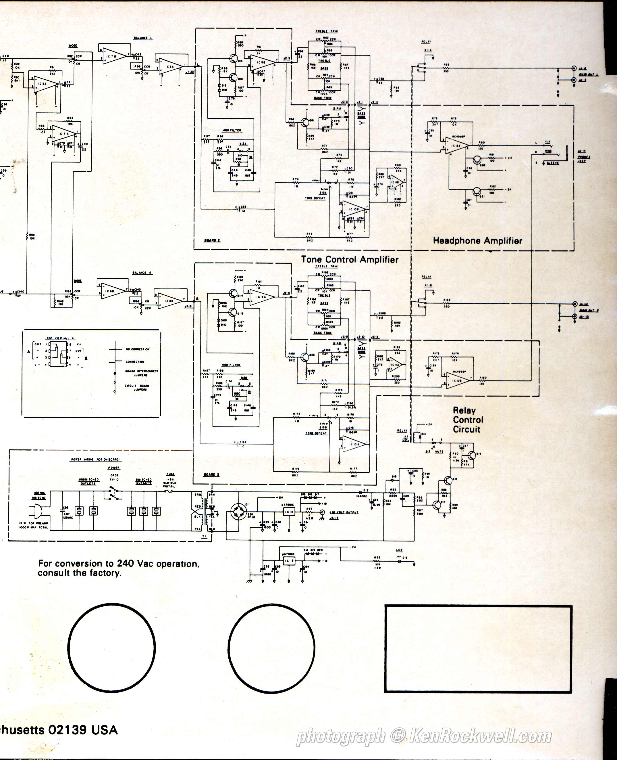
Apt Holman Preamplifier Service Manual.
Help me help you top
I support my growing family through this website, as crazy as it might seem.
The biggest help is when you use any of these links to Adorama, Amazon, eBay, B&H, when you get anything, regardless of the country in which you live. It costs you nothing, and is this site's, and thus my family's, biggest source of support. These places have the best prices and service, which is why I've used them since before this website existed. I recommend them all personally.
If you find this page as helpful as a book you might have had to buy or a workshop you may have had to take, feel free to help me continue helping everyone.
If you've gotten your gear through one of my links or helped otherwise, you're family. It's great people like you who allow me to keep adding to this site full-time. Thanks!
If you haven't helped yet, please do, and consider helping me with a gift of $5.00.
As this page is copyrighted and formally registered, it is unlawful to make copies, especially in the form of printouts for personal use. If you wish to make a printout for personal use, you are granted one-time permission only if you PayPal me $5.00 per printout or part thereof. Thank you!
Thanks for reading!
Mr. & Mrs. Ken Rockwell, Ryan and Katie.
Home Donate New Search Gallery Reviews How-To Books Links Workshops About Contact